

(Click on any picture for a bigger version)
The PDP-10/X is a reimplementation of the PDP-10, with 512KW of memory, a line-frequency clock, an interface to an RS-232 terminal, and an interface to an ATA-2 disk, that I designed and built just for fun.
I'd always wanted to design a PDP-10, and in the course of designing and building the PDP-10/X, I ended up designing three of them, but only building the last one.
The first design was microcoded, and could (more or less) run executive mode software for the KS10. It was done so long ago that I was concerned about getting the processor to fit in a single FPGA, so the design used a 18-bit double-pumped data path, controlled by a large highly-vertical microprogram stored in three 32Kx8 10ns SRAMs. The design compensated somewhat for the extra cycles need to perform 36-bit operations with an 18-bit data path by running fast; the micromachine was pipelined, with three microinstructions in flight at the same time. Some parts of this design worked out surprisingly well (there is a lot of 18-bitness in the PDP-10 instruction set), but other parts (long shifts, the 72-bit operands in multiply and divide, floating point) were very awkward.
I wrote a microcode simulator and all of the microcode for this machine, and got it pass all of the relevant diagnostics from KLAD, and to run a slightly modified version of KS10 ITS (the I/O devices were not the same as the KS10's I/O devices, so all of the I/O drivers needed to be hacked, but all of the memory management code was run unchanged. I then wrote the verilog, and got it to pass a few simple diagnostics.
In designing this machine, I noticed that there were many places were ITS did somewhat odd things to work on the KS10-like machine; in many places the combination of the KA10 code and the external ITS pager just seemed to work out better. This got me thinking along a different path; imagine a world in which there was a new model of PDP-10, based off the KA10, which was designed to run ITS. I spent a long time carefully reading the ITS code and figuring out how the KA10 ITS pager worked, and then designed a new executive mode architecture for a KA10-like processor for ITS. I cleaned up a few things (for example, executive mode and user mode have separate trap enables and can service the traps at different PI levels), but most of the design has a very KA10-like feel.
I wrote a simulator for the new machine (in which the registers and flows of the eventual hardwired design were very visible) and got it to pass all of the relevant diagnostics from KLAD (which was a bit of a chore, since the KA10 manuals are not crystal clear how corner cases in complicated instructions, like FDVL, actually work). I then added a new set of conditionals to ITS, and got ITS to run as well (the new code was always very similar to the KA10 code, but in some places it was actually a little nicer, because anytime things didn't work really well, I changed the design so it did work really well).
I then wrote all the verilog for the design. I was unsure how big the design was going to be, and I wanted the FPGAs to place-and-route quickly, so I partitioned the design into three FPGAs, connected by a simple synchronous bus. The CPU FPGA contained the processor (including all of the logic associated with the PI system). The PAG FPGA contained the pager and the memory controller (when an address was placed on the bus a bit indicated if it was a virtual address or a physical address, so the PAG FPGA could determine if translation was needed). The BIO FPGA contained the line-frequence clock, the console terminal interface, and the disk interface. I got the verilog to pass all of the relevant diagnostics from KLAD, embelished with a new diagnostic for my new executive mode architecture.
Towards the end of the second design, when I was actually building the FPGAs to ensure that there would be no suprises, I realized that the PAG FPGA and the BIO FPGA were almost completely empty and that everything (CPU, PAG, and BIO) could actually fit in a single XC3S500E device. Three FPGAs worth of logic were collapsed into one FPGA, and the design described here was finished.
The PDP-10/X System Manual describes the archtecture of the system. This document is now done in LaTeX. The original (and now slightly out-of-date) version of this document is still available here.
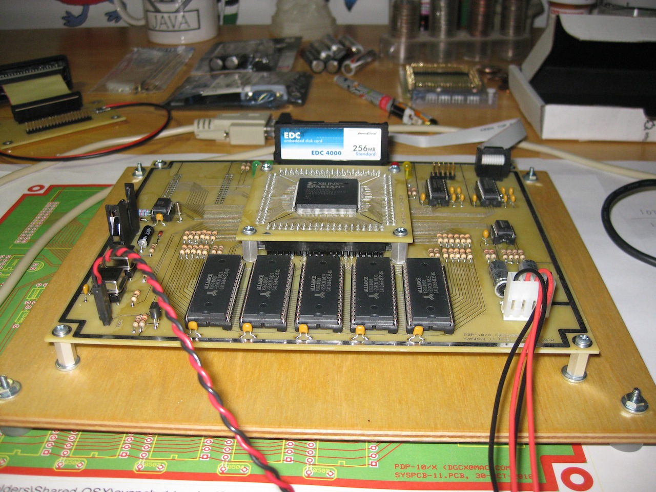
There are two PCB designs. Both are two-sided designs, and both were built at Express PCB.
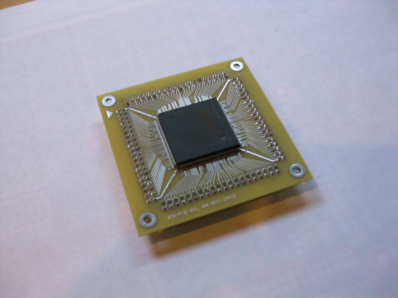
The FPGA PCB is a general-purpose FPGA board that I designed some time ago (but I tweaked it a little for use in the PDP-10/X). It is little more than a carrier for a XILINX SPARTAN-3E FPGA (XC3S500E-4) in a PQFP-208 package, along with the bypass capacitors, and the LDOs that generate the 2.5V (VDDAUX) and 1.2V (VDDINT) supplies. All of the I/O pins are powered by 3.3V.
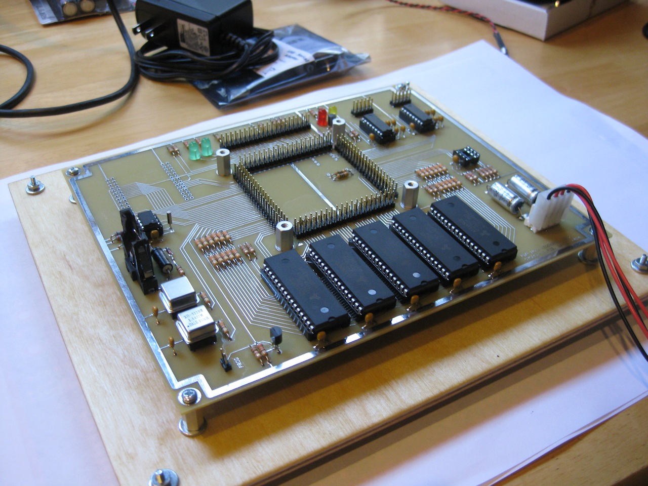
The system PCB contains:
All of the parts for the PDP-10/X have been sitting in a pile in my workroom for some time, including the blank PCBs. This week was Thanksgiving shutdown, so I got some time to assemble things (I say some time because we got a new puppy three weeks ago, and the puppy requires a lot of attention as well).
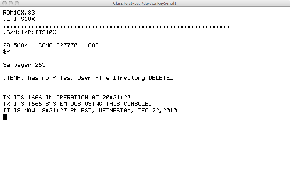
Everything came to life as soon as power was applied.
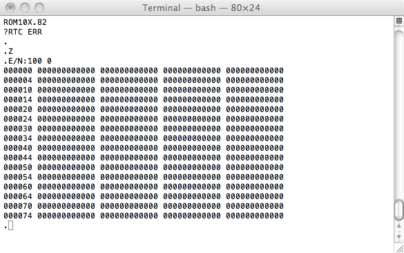
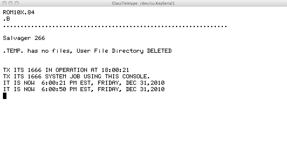
The ROM types it's name and version, then it types an "?RTC ERR" message (because the RTC has not been initialized), then it prompts for input. At this point the system has executed a lot of PDP-10 instructions (since the ROM is, in fact, a PDP-10 program, running out of the high moby of memory). The "Z" command clears the low moby of memory, and the "E/N:100 0" command shows that at least some of the low moby has been cleared.
I then used the ROM to deposit a short program that adds up the first 100 integers into memory. This program, which I extracted from one of the verilog test benches, was the first non-trivial program that the processor ever executed.
/*
initial begin
//  001000, main
w(19'o001000, 36'o200740001025);        //  main:   move 17,pdl
w(19'o001001, 36'o400000000000);        //          setz 0
w(19'o001002, 36'o201040000144);        //          movei 1,144
w(19'o001003, 36'o270000000001);        //  x0:     add 0,1
w(19'o001004, 36'o366040001003);        //          sojn 1,x0
w(19'o001005, 36'o260740001013);        //          pushj 17,pdec
w(19'o001006, 36'o201000000015);        //          movei 0,15
w(19'o001007, 36'o260740001021);        //          pushj 17,pchr
w(19'o001010, 36'o201000000012);        //          movei 0,12
w(19'o001011, 36'o260740001021);        //          pushj 17,pchr
w(19'o001012, 36'o254200001000);        //  x1:     jrst 4,x1
//  001013, pdec
w(19'o001013, 36'o231000000012);        //  pdec:   idivi 0,12
w(19'o001014, 36'o261740000001);        //          push 17,1
w(19'o001015, 36'o332000000000);        //          skipe 0
w(19'o001016, 36'o260740001013);        //          pushj 17,pdec
w(19'o001017, 36'o262740000000);        //          pop 17,0
w(19'o001020, 36'o271000000060);        //          addi 0,60
//  001021, pchr
w(19'o001021, 36'o720340000400);        //  pdec:   conso tty,400
w(19'o001022, 36'o254000001021);        //          jrst pchr
w(19'o001023, 36'o720140000000);        //          datao tty,0
w(19'o001024, 36'o263740000000);        //          popj p,
//  001025, -10,s-1
w(19'o001025, 36'o777766001025);        //  pdl:    xwd -10,s-1
end
*/

There is no prompt because the program halted the processor (and yes, the RUN LED did go out). The only way out of this state is to push the reset button.
All of the processor diagnostics, which had passed in simulation, pass on the hardware.
All of the debugging was getting the command in the ROM that downloads DECSAV files to work. This command was one of the few things that had not been tested in simulation, and it was buggy. The routine that read 36-bit words encoded as five bytes from the serial line assumed that the bytes were in little-endian order, when, in fact, they were actually in big-endian order (why this routine was written in this way is a mystery, since the bytes were always in big-endian order), and the main loop of the loader was missing a JRST, so it read one data block, and then died.
The DS1337 real-time clock works. I wrote a (downloadable) program that implemented commands to read and write the registers of the DS1337, and when that appeared to work, added commands to get and set the date and time. When the date and time are set the console ROM does not complain about an "?RTC ERR".
I have not yet tried powering the real-time clock chip from the coin cell, but it's hard to imagine that it won't work, given that the battery holder and the diode don't seem to be installed backwards.
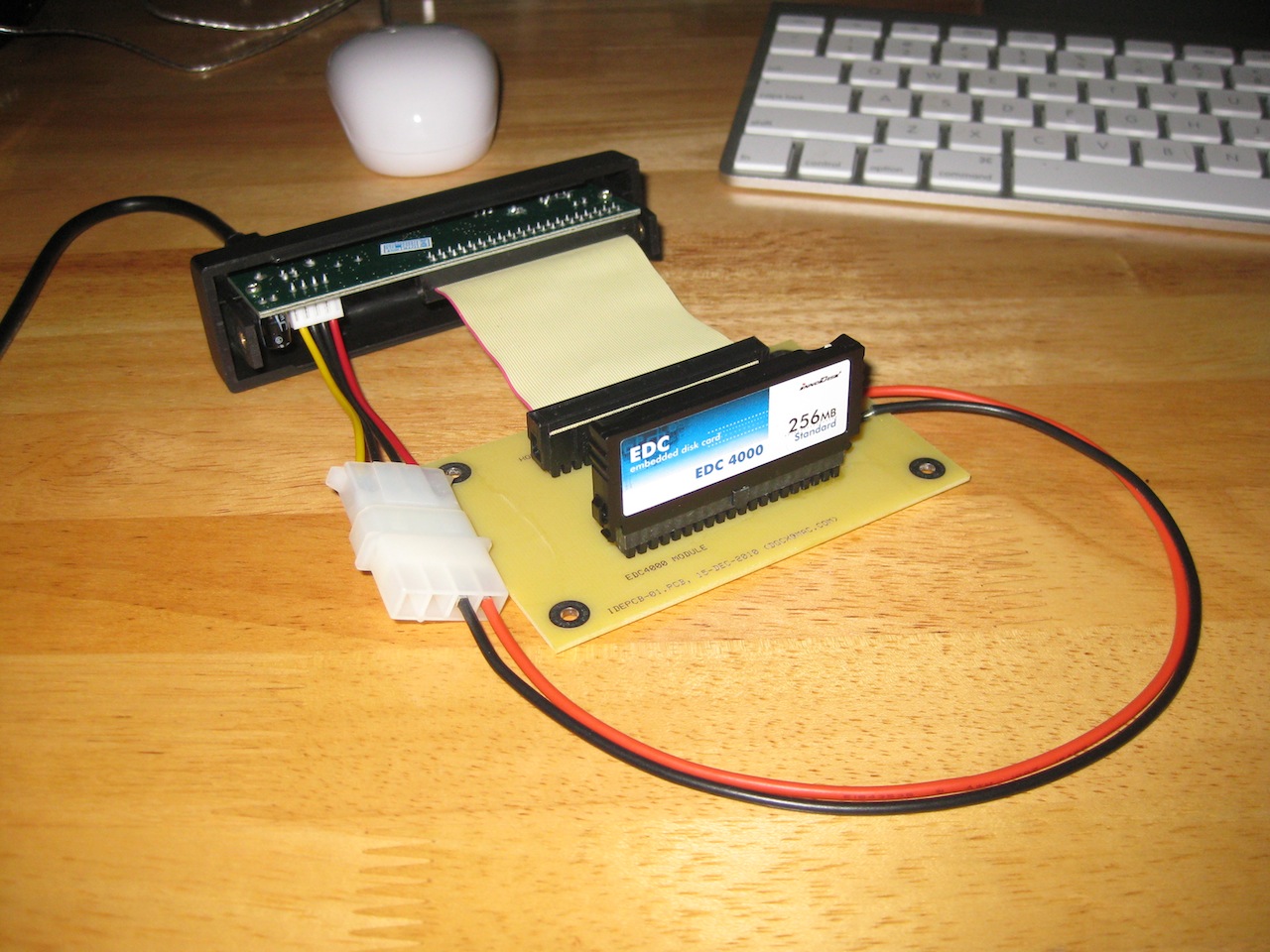
An InnoDisk EDC4000 disk-on-module card is designed so that it can be plugged directly onto a (male) connector on a PC motherboard. This means it cannot be plugged into a USB/ATA interface board from a USB disk enclosure, because those boards are all designed to plug directly into the (male) connector on an ATA disk, and those boards all have captive cables because it saves money. A little male-to-male adaptor card deals with this problem, and also feeds power into the disk-on-module (on pin 20, which the ATA standard uses for a key).
ITS runs.
At first boot it got a horrible disk error. After some debugging I discovered that if I patched out the CONO APR instruction in NSALV that resets the I/O system, the horrible disk error goes away. The CONO APR also resets the disk, and although it takes a long time for an ATA disk to finish a reset sequence, I thought that the disk driver, which began with a spin loop waiting for BSY=0 and DRDY=1, would stall if the disk was still resetting. More debugging is needed.
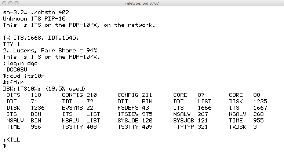
Startup.
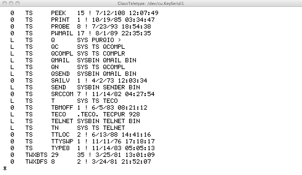
A directory listing.
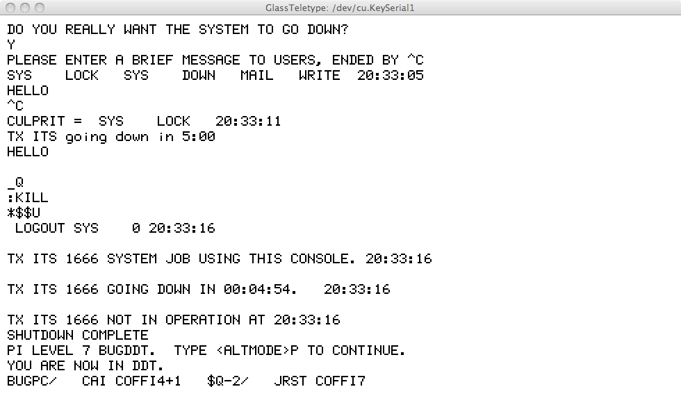
Shutdown.
The patch is no longer needed. I changed the code surrounding the CONO APR instruction in NSALV that resets the I/O system so that it drains the transmit side of the TTY device before it does the reset, and so that it waits for the DSK device to be ready to accept commands after it does the reset.
The first change is needed because the length of the reset (25us) is short compared to the length of a character, and so if you reset the transmit side of the TTY device in the middle of a character, and immediately send another character, the receiver will interpret the start of the first character sent after the reset as part of the last character sent before the reset, resulting in a garbage character or a framing error, depending on the receiver's luck. Furthermore, if you keep sending characters, the receiver can remain misaligned, generaing a stream of garbage characters or framing errors, until the characters stop.
The second change is needed because the disk driver writes the device/head register (selecting the unit and LBA mode) before it waits for BSY=0 and DRDY=1. When the disk transitions from not-ready to ready after a reset it sets the device/head register to 0, as required by the ATA specification, selecting CHS mode. The first disk operation after a reset ends up being executed in CHS mode even though the disk address registers have been loaded assuming the operation will be executed in LBA mode. The result is a "sector not found" error reading the first TUT block.
The hardware was changed to make it easier for software to drain the transmit side of the TTY device before a reset. A new read-only CONI bit (TA) is 1 if the transmit side of the TTY device is active (holding register or shift register full). The ROM, which needed to drain the transmit side of the TTY device but did so with an ugly hack, was revised to use this new hardware as well.
ITS now uses all 250MB of the disk-on-module (as opposed to the first 32MB of it). This required changing a bunch of definitons in NSALV and ITS, and adding some additional options to the tools I use to manipulate disk images on OSX.
Having more space means more software can be loaded onto the disk. My terminal emulator looks like a VT52 to which insert-line and delete-line have been added, so ITS knows how to drive it without the use of CRTSTY (the terminal type is sey by :TCTYP VT52,+%TOLID), so EMACS works.
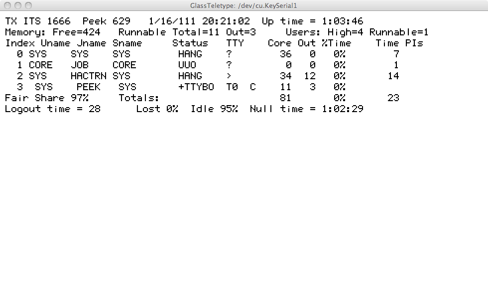
PEEK works too (after it re-purifies itself).
ITS now includes support for the CHAOSNET (or, to be more precise, CHAOSNET encapsulated in IP using protocol type 16 carried over the ethernet; a CHAOSNET node with address A.B has IP address 192.168.A.B).
The ethernet controller is the WIZNET W5300, mounted on the standard WIZ830MJ evaluation board. This controller was chosen because it has a simple parallel interface and a large packet buffer (128KB), but in the end, the fact that it understood how to do higher-level protocols (IP, ICMP, UDP, TCP) by itself turned out to be useful (the CHAOSNET implementation uses the controllers RAW-IP mode, and the controller handles all of the details of ICMP and ARP more or less by itself).
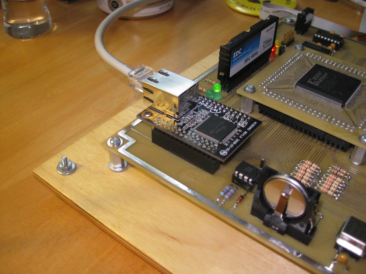
The 8-bit indirect address mode of the controller is used, mainly because the FPGA was very tight on pins (in this mode, only three address bits and eight data bits are needed). The hardware allows software to read and write 16-bit and 32-bit quantities, and to specifiy if the two bytes in each 16-bit quantity should be in big-endian or little-endian order (CHAOSNET uses both orders, depending on context)
A simple version of TELNET, modified to include a user-mode implementation of the CHAOSNET protocol using raw sockets, was used to debug the new code in ITS. The bulk of the debugging time was spent figuring out how the W5300 works (the chip actually works quite well, but the data sheet does not describe the tricky bits clearly, if it describes them at all). The fact that the user-mode impementation of the CHAOSNET protocol uses raw sockets means that TELNET needs to be run as the super-user, which is a bit of a nuisence (now that I really understand how the W5300 works it is clear that UDP and a fixed port would have worked, and I will probably change to doing this soon).
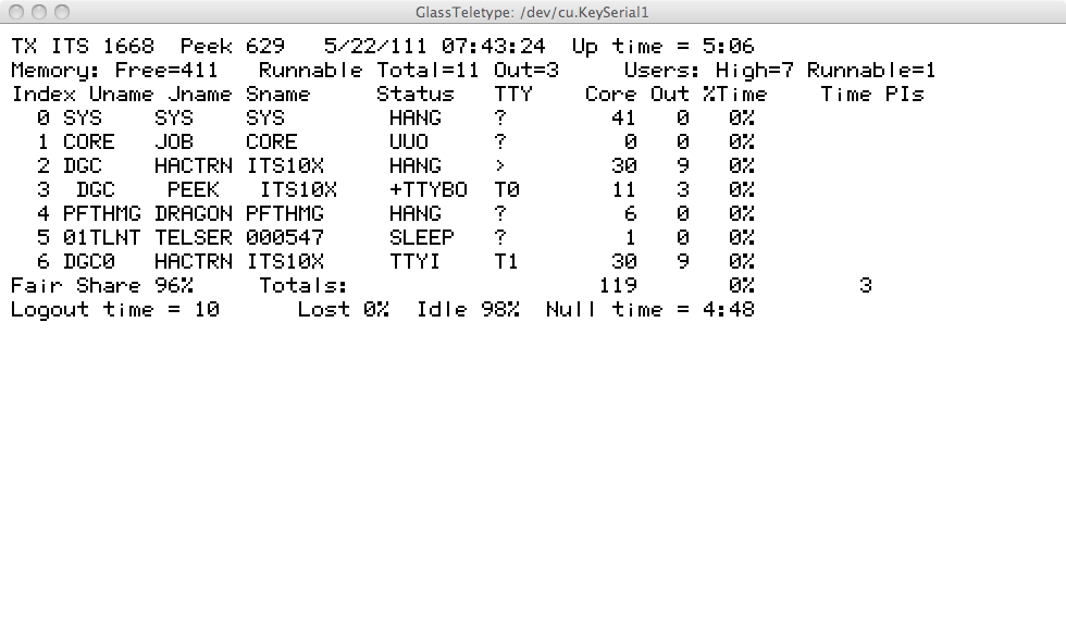
Here's TELNET talking to ITS (I am assuming that it's an unknown ITS because I have not added TX to some table in TELSER).
Here's PEEK on the console at the same time.
It's been a very long time since I have posted an update. Things have been happening, but there have been a lot of other demands on my time, and so things have been happening slowly.
I now have a compelete set of tools for manipulating ITS disk images, be they in a file, on a physical disk, or on a physical disk on the other end of the network. The ability to manipulate a disk image over the network (with the assistance of a stand-alone PDP-10 program that uses the TCP mode of the W5300) allows a new system and/or a whole new disk image to be installed onto the PDP-10/X without having to remove the disk from the system.
The CHAOSNET library has been revisied to support multiple connections at the same time and to support both client and server connections. Server connections were debugged with a simple TELNET server, running on OSX, that works over the CHAOSNET. Connecting to a UNIX machine with TELNET from an ITS machine seems strange.
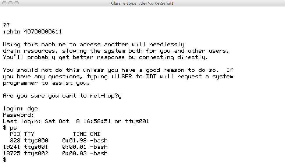
The big octal number in the CHTN command is a network address; the 4 means "not the internet", the 7 means CHAOSNET, and the 611 is the CHAOSNET address (the target machine has IP address 192.168.1.137)
Because the CHAOSNET library has been revisied to support both client and server connections it is possible to write a file transfer client that uses the CHAOSNET FILE protocol. Having this program is very convenient, because it makes it possible to update a small number of files on the PDP-10/X without reloading the whole disk.
Today is the first day of daylight time, and the new code I added to ITS to deal with the most modern daylight time rules did the correct thing.
Moved this web site away from MobileMe web hosting, which goes away as a side effect of the MobileMe to iCloud transition.
Updated: April 24, 2012
dgc@fpgaretrocomputing.org